Section engineering
Inflatable Seal Profiles and Valves
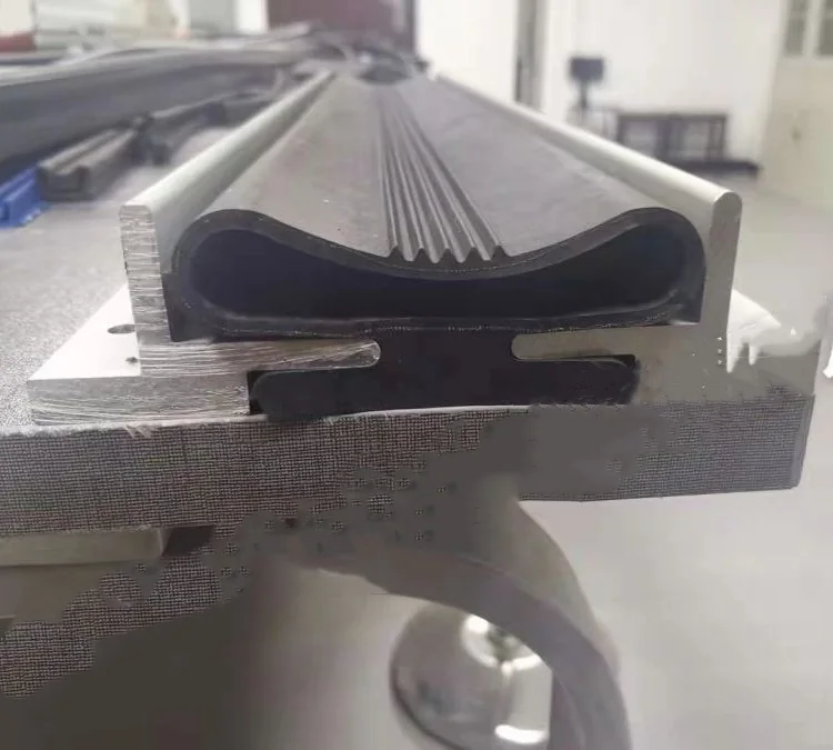
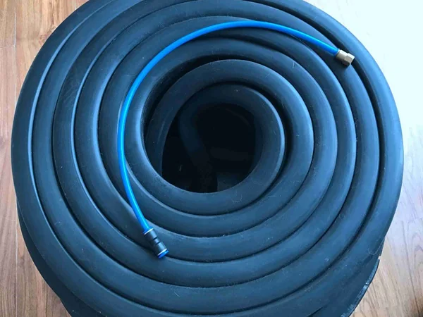
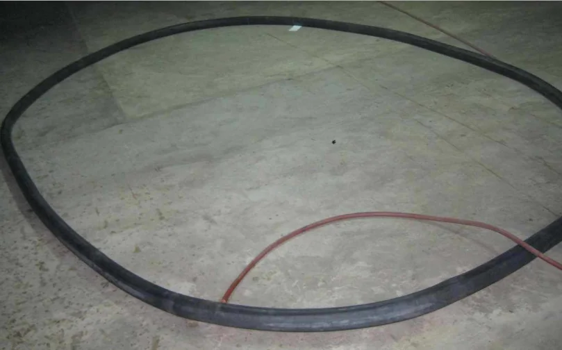
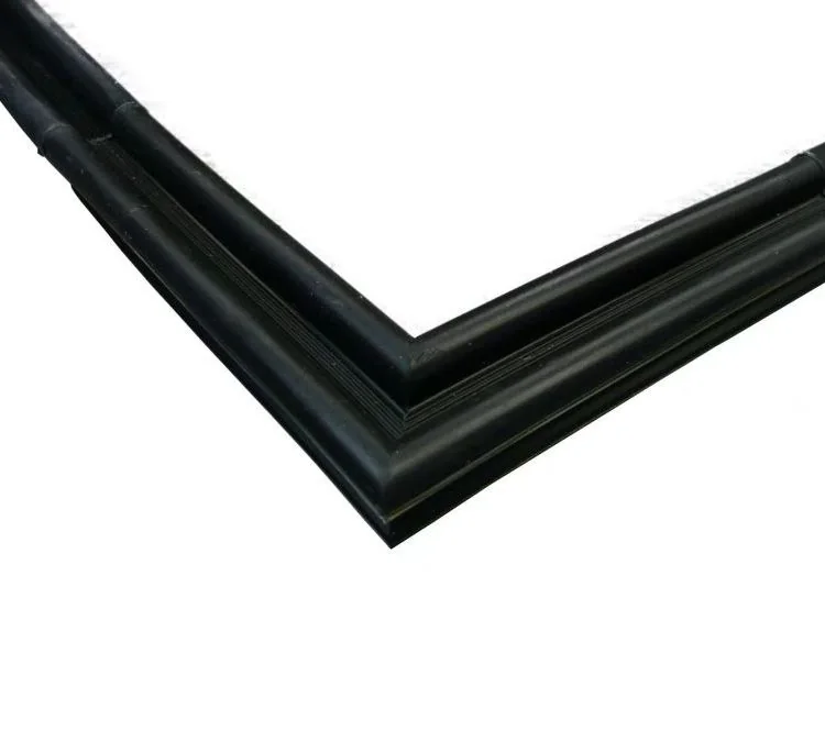
Profile geometry and inflation hardware coordinated for the required direction of movement, installation space and service access.
Discuss your applicationProduct views
Selected product images
Engineering data
Specifications
Final values are confirmed against the drawing, operating conditions and prototype test results.
- Expansion direction
- Axial, radially outward or radially inward
- Retention
- Groove-retained arrangement selected with the uninflated profile envelope
- Valve layout
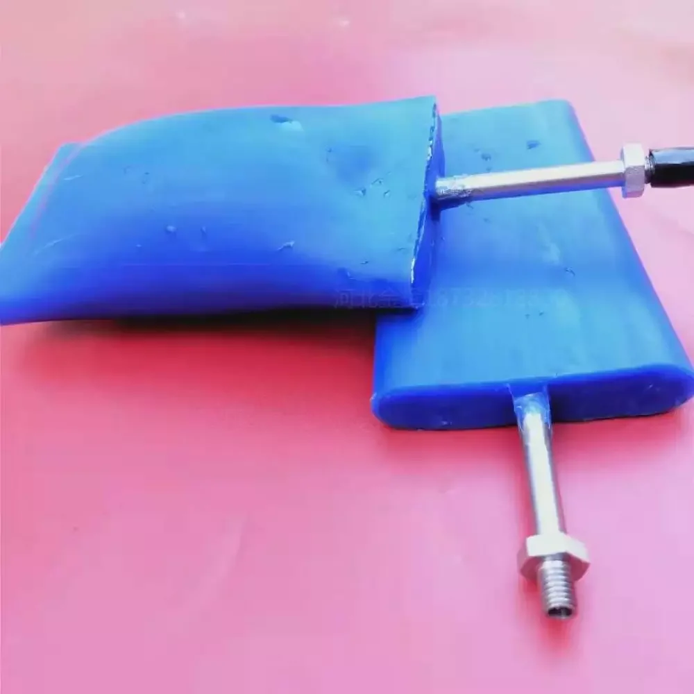
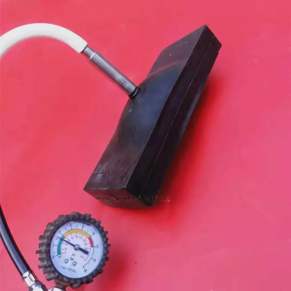
- Straight, angled or remote connection subject to space and routing review
- Corner layout
- Corner radius and joint position reviewed for the selected section
- Dimensions
- Profile and finished ring or frame geometry made to drawing

Material selection
Material options
Material selection depends on temperature, medium, cleaning method, cycle rate and regulatory requirements.
Silicone
A candidate for projects where flexibility, temperature capability or clean processing is important.
Confirm the actual compound against media, cleaning and regulatory requirements.EPDM
A candidate for water, weathering and selected process environments.
Review oil and chemical exposure before selection.NBR
A candidate where oil resistance is a key part of the duty.
Check temperature, ozone and cleaning exposure for the selected grade.Operating principle
How it works
Profile geometry determines whether inflation movement is axial, radially outward or radially inward. The useful direction must point from the retaining groove toward the mating surface.
When deflated, the profile must retract far enough to avoid abrasion during opening, product movement or cleaning access. Valve routing must avoid sharp bends and local interference.
Use cases
Applications
Profile and valve configurations are developed for doors, hatches, transfer equipment, process closures and other assemblies where the available groove and sealing direction differ.
Selection starts from the equipment interface rather than from a profile picture alone.
Made to drawing
Custom manufacturing
Provide a section through the groove and mating surface, the available corner radius, minimum and maximum gap, finished geometry and preferred valve location.
The profile envelope, expansion direction, joint position and air connection can then be coordinated.
Production
Manufacturing approach
The finished ring or frame is produced only after the profile section, corner limits and valve arrangement are approved.
Joining and forming details are selected for the final geometry rather than treated as independent catalogue options.
Verification
Quality control
Profile dimensions, finished geometry, corner condition, joint and valve placement should be inspected against the approved drawing.
Inflation and retraction should be checked in a representative groove before production approval.
Delivery
Packaging and shipping
Profiles and finished seals should be protected from sharp folds, crushing and damage to the inflation connection.
Packing arrangement is confirmed from the section size and finished geometry.
Buyer decisions
Technical FAQ
How do I choose the expansion direction of an inflatable seal profile?
Choose the direction from the groove location and the mating surface. Axial, radially outward and radially inward profiles solve different interfaces; the section drawing must show where the retained profile starts and where contact is required.
What groove information should be included in the RFQ?
Include groove width and depth, edge radii, mating-surface position, minimum and maximum gap, available corner radius, deflated clearance and the route available for the air connection.
Can the valve position and connection style be changed?
Yes, subject to profile and installation review. The connection must remain accessible, avoid sharp tube bends and not create a local interference point when the seal inflates or retracts.
Why does the corner radius matter for an inflatable profile?
A tight corner can restrict inflation, distort the section or concentrate stress near the bend and joint. The available radius should be reviewed with the selected cross-section before the finished seal is approved.